Diagrama de topologia
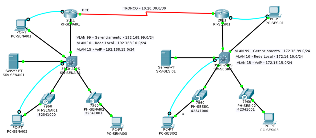
Tabela de endereçamento fixo
| Dispositivo | Interface | Endereço IP | Máscara de sub-rede | Gateway padrão |
| SW-SENAI01 | VLAN99 | 192.168.99.1 | 255.255.255.0 | N/A |
| RT-SENAI01 | Fa0/0.10 | 192.168.10.254 | 255.255.255.0 | N/A |
| RT-SENAI01 | Fa0/0.15 | 192.168.15.254 | 255.255.255.0 | N/A |
| RT-SENAI01 | VLAN99 | 192.168.99.2 | 255.255.255.0 | N/A |
| SRV-SENAI01 | Fa0 | 192.168.10.250 | 255.255.255.0 | 192.168.10.254 |
| SW-SESI01 | VLAN99 | 172.16.99.1 | 255.255.255.0 | N/A |
| RT-SESI01 | Fa0/0.10 | 172.16.10.254 | 255.255.255.0 | N/A |
| RT-SESI01 | Fa0/0.15 | 172.16.15.254 | 255.255.255.0 | N/A |
| RT-SESI01 | VLAN99 | 172.16.99.2 | 255.255.255.0 | N/A |
| SRV-SESI01 | Fa0 | 172.16.10.250 | 255.255.255.0 | 172.16.10.254 |
Os outros dispositivos vão receber IP pelo serviço de DHCP.
OBJETIVOS DE APRENDIZAGEM
- Configurar topologia física de rede para telefonia IP
- Configurar VLANs de gerenciamento
- Configurar um servidor de DHCP
- Configurar um serviço de telefonia
- Associar os ramais aos telefones
- Simular uma ligação de telefonia IP
- Simular a ligação entre duas centrais telefônicas
INTRODUÇÃO
Esta atividade vai ensinar como configurar o serviço de telefonia IP em um ambiente cisco, explorando novos comandos e interligando duas centrais telefônicas distintas. Também vai ensinar como configurar um servidor de DHCP para telefones IP.
TAREFA 1 – CONFIGURAR TOPOLOGIA FÍSICA
Etapa 1 – Selecionar os dispositivos
- Abra a parte I e utilize para desvolver o lado da SESI da rede.
- Monte o mesmo diagrama no Cisco Packet Tracer conforme imagem acima, representando a rede SESI ao lado do diagrama do SENAI.
Etapa 2 – Cabear a rede
- Conectar a interface Fa0/0 de RT-SESI01 à interface Fa0/24 de SW-SESI01
- Conectar a interface Fa0/1 de SW-SESI01 à interface Fa0 de PC-SESI01
- Conectar a interface Fa0/2 de SW-SESI01 à interface de Switch do telefone PH-SESI01
- Conectar a interface Fa0/3 de SW-SESI01 à interface de Switch do telefone PH-SESI02
- Conectar a interface PC do telefone PH-SESI01 à interface Fa0 do PC-SESI02
- Conectar a interface PC do telefone PH-SESI02 à interface Fa0 do PC-SESI03
- Conectar a interface Fa0 de SRV-SESI01 à interface Fa0/4 de SW-SESI01
- Conectar a interface RS 232 de PC-SESI01 a inter face de Console de RT-SESI01
- Conectar a interface RS 232 de PC-SESI02 a inter face de Console de SW-SESI01
Etapa 3 – Nomear e colocar legendas no diagrama
- Altere o Display Name dos PCs conforme o diagrama de topologia acima.
- Coloque em legendas os números de telefone embaixo dos telefones
- Coloque as legendas descritivas de VLANs conforme o diagrama de topologia acima.
TAREFA 2 – CONFIGURAR IP DO SERVIDOR DE DNS
Um serviço de DNS normalmente é configurado em um servidor. Portanto, temos no diagrama o servidor SRV-SENAI01, que em uma rede real, serviria como máquina principal de resolução de nomes na rede.
Etapa 1 – Configurar o IP do Servidor
- Dê um duplo clique em SRV-SESI01 e, navegue até a guia DESKTOP
- Dê um duplo clique em IP CONFIGURATION
- Configure os campos conforme imagem abaixo
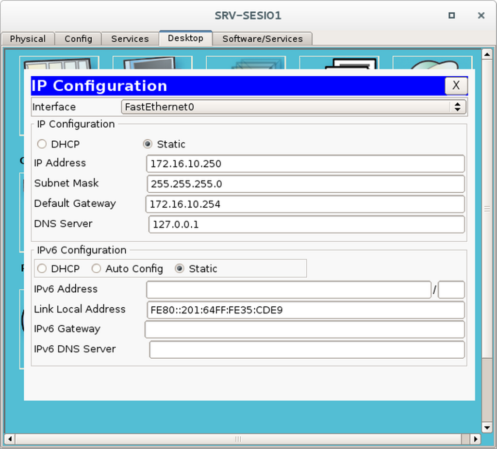
Note que o IP do DNS Server aponta para ele mesmo (127.0.0.1). Sempre devemos configurar um servidor que hospeda um serviço de DNS dessa forma.
TAREFA 3 – CONFIGURAR O SW-SESI01
Etapa 1 – Fazer a configuração básica
Vá no PC-SESI02, dê um duplo clique e acesse guia Desktop. Clique em terminal e depois clique em OK.
Switch>enable
Switch#conf t
Enter configuration commands, one per line. End with CNTL/Z.
Switch(config)#hostname SW-SESI01
SW-SESI01(config)#no ip domain lookup
SW-SESI01(config)#service password-encryption
SW-SESI01(config)#enable secret sw*123
SW-SESI01(config)#line console 0
SW-SESI01(config-line)#password console*123
SW-SESI01(config-line)#login
SW-SESI01(config-line)#exit
SW-SESI01(config)#line vty 0 4
SW-SESI01(config-line)#password vty*123
SW-SESI01(config-line)#login
SW-SESI01(config-line)#exit
SW-SESI01(config)#ip default-gateway 172.16.10.254
Etapa 2 – Configurar um aviso de acesso
Um aviso de acesso permite identificarmos no acesso remoto se estamos acessando o dispositivo correto da rede.
SW-SESI01(config)#banner motd &
Enter TEXT message. End with the character '&'.
************************************************
 !!!SW-SESI01 - ACESSO RESTRITO!!!
************************************************
&
Etapa 3 – Criar as VLANs
SW-SESI01(config)#vlan 10
SW-SESI01(config-vlan)#name VLAN-Rede-Local
SW-SESI01(config-vlan)#exit
SW-SESI01(config)#vlan 15
SW-SESI01(config-vlan)#name VLAN-VoIP
SW-SESI01(config-vlan)#exit
SW-SESI01(config)#vlan 99
SW-SESI01(config-vlan)#name VLAN-Gerenciamento
SW-SESI01(config-vlan)#exit
Etapa 4 – Configurar a VLAN de Gerenciamento
SW-SESI01(config)#
SW-SESI01(config)#interface VLAn 1
SW-SESI01(config-if)#no ip address
SW-SESI01(config-if)#shutdown
SW-SESI01(config-if)#exit
SW-SESI01(config)#interface vlan 99
SW-SESI01(config-if)#
%LINK-5-CHANGED: Interface Vlan99, changed state to up
SW-SESI01(config-if)#ip address 172.16.99.1 255.255.255.0
SW-SESI01(config-if)#exitEtapa 5 – Configurar as interfaces
SW-SESI01(config)#
SW-SESI01(config)#interface range fastEthernet 0/1-23
SW-SESI01(config-if-range)#switchport access vlan 10
SW-SESI01(config-if-range)#switchport mode access
SW-SESI01(config-if-range)#switchport voice vlan 15
SW-SESI01(config-if-range)#exit
SW-SESI01(config)#
SW-SESI01(config)#interface fastEthernet 0/24
SW-SESI01(config-if)#switchport trunk native vlan 99
SW-SESI01(config-if)#switchport trunk encapsulation dot1q
SW-SESI01(config-if)#switchport mode trunk
SW-SESI01(config-if)#exitEtapa 6 – Verificar se as VLANs foram criadas
SW-SESI01#show vlan briefVLAN Name                         Status    Ports
---- ---------------------------- --------- -------------------------------
1    default                      active    Gig0/1, Gig0/2
10   VLAN-Rede-Local              active    Fa0/1, Fa0/2, Fa0/3, Fa0/4
                                            Fa0/5, Fa0/6, Fa0/7, Fa0/8
                                            Fa0/9, Fa0/10, Fa0/11, Fa0/12
                                            Fa0/13, Fa0/14, Fa0/15, Fa0/16
                                            Fa0/17, Fa0/18, Fa0/19, Fa0/20
                                            Fa0/21, Fa0/22, Fa0/23
15   VLAN-VoIP                    active
99   VLAN-Gerenciamento           active
1002 fddi-default                 act/unsup
1003 token-ring-default           act/unsup
1004 fddinet-default              act/unsup
1005 trnet-default                act/unsup
Etapa 7 – Verificar se a VLAN 99 foi conigurada
SW-SESI01#show interfaces vlan 99
Vlan99 is up, line protocol is up
  Hardware is CPU Interface, address is 00d0.bab5.d083 (bia 00d0.bab5.d083)
  Internet address is 172.16.99.1/24
  MTU 1500 bytes, BW 100000 Kbit, DLY 1000000 usec, reliability 255/255, txload 1/255, rxload 1/255
  Encapsulation ARPA, loopback not set
  ARP type: ARPA, ARP Timeout 04:00:00
  Last input 21:40:21, output never, output hang never
  Last clearing of "show interface" counters never
  Input queue: 0/75/0/0 (size/max/drops/flushes); Total output drops: 0
  Queueing strategy: fifo
  Output queue: 0/40 (size/max)
  5 minute input rate 0 bits/sec, 0 packets/sec
  5 minute output rate 0 bits/sec, 0 packets/sec
     1682 packets input, 530955 bytes, 0 no buffer
     Received 0 broadcasts (0 IP multicast)
     0 runts, 0 giants, 0 throttles
     0 input errors, 0 CRC, 0 frame, 0 overrun, 0 ignored
     563859 packets output, 0 bytes, 0 underruns
     0 output errors, 23 interface resets
     0 output buffer failures, 0 output buffers swapped out
Etapa 8 – Salvar as configurações
SW-SESI01#write
Building configuration...
[OK]
SW-SESI01#
TAREFA 4 – CONFIGURAR O ROTEADOR RT-SESI01
Etapa 1 – Fazer a configuração básica
Vá no PC-SENAI01, dê um duplo clique e acesse guia Desktop. Clique em terminal e depois clique em OK.
Router>enable
Router#conf t
Enter configuration commands, one per line. End with CNTL/Z.
Router(config)#hostname RT-SESI01
RT-SESI01(config)#no ip domain lookup
RT-SESI01(config)#service password-encryption
RT-SESI01(config)#enable secret rt*123
RT-SESI01(config)#line console 0
RT-SESI01(config-line)#password console*123
RT-SESI01(config-line)#login
RT-SESI01(config-line)#exit
RT-SESI01(config)#line vty 0 4
RT-SESI01(config-line)#password vty*123
RT-SESI01(config-line)#login
RT-SESI01(config-line)#exit
Etapa 2 – Configurar um aviso de acesso
Um aviso de acesso permite identificarmos no acesso remoto se estamos acessando o dispositivo correto da rede.
RT-SESI01(config)#banner motd &
Enter TEXT message. End with the character '&'.
************************************************
 !!!RT-SESI01 - ACESSO RESTRITO!!!
************************************************
&
Etapa 3 – Configurar as interfaces
RT-SESI01(config)#interface fastEthernet 0/0
RT-SESI01(config-if)#no shutdown
RT-SESI01(config-if)#exit
RT-SESI01(config)#interface fastEthernet 0/0.99
RT-SESI01(config-subif)#description #Sub-Interface de Gerenciamento#
RT-SESI01(config-subif)#encapsulation dot1Q 99 native
RT-SESI01(config-subif)#ip address 172.16.99.2 255.255.255.0
RT-SESI01(config-subif)#exitRT-SESI01(config)#interface fastEthernet 0/0.10
RT-SESI01(config-subif)#description #Sub-Interface da VLAN de Rede Local#
RT-SESI01(config-subif)#encapsulation dot1Q 10
RT-SESI01(config-subif)#ip address 172.16.10.254 255.255.255.0
RT-SESI01(config-subif)#exitRT-SESI01(config)#interface fastEthernet 0/0.15
RT-SESI01(config-subif)#description #Sub-Interface da VLAN de VoIP#
RT-SESI01(config-subif)#encapsulation dot1Q 15
RT-SESI01(config-subif)#ip address 172.16.15.254 255.255.255.0
RT-SESI01(config-subif)#exitEtapa 4 – Verificar a configuração das interfaces
RT-SESI01#show ip interface brief
Interface          IP-Address    OK? Method Status                Protocol
FastEthernet0/0    unassigned    YES unset  up                    up
FastEthernet0/0.10 172.16.10.254 YES manual up                    up
FastEthernet0/0.15 172.16.15.254 YES manual up                    up
FastEthernet0/0.99 172.16.99.2   YES manual up                    up
FastEthernet0/1    unassigned    YES unset  administratively down down
Vlan1              unassigned    YES unset  administratively down down
Etapa 5 – Configurar o serviço de DHCP para as VLANs
RT-SESI01(config)#ip dhcp excluded-address 172.16.10.250
RT-SESI01(config)#ip dhcp excluded-address 172.16.10.254
RT-SESI01(config)#ip dhcp excluded-address 172.16.15.254
RT-SESI01(config)#ip dhcp pool rede-local-senai
RT-SESI01(dhcp-config)#network 172.16.10.0 255.255.255.0
RT-SESI01(dhcp-config)#default-router 172.16.10.254
RT-SESI01(dhcp-config)#dns-server 172.16.10.250
RT-SESI01(dhcp-config)#exitRT-SESI01(config)#ip dhcp pool rede-voip-senai
RT-SESI01(dhcp-config)#network 172.16.15.0 255.255.255.0
RT-SESI01(dhcp-config)#default-router 172.16.15.254
RT-SESI01(dhcp-config)#option 150 ip 172.16.15.254
RT-SESI01(dhcp-config)#exitEtapa 6 – Verificar a distribuição de IPs
Lembre-se que a rede 172.16.10.0 é para computadores, e a rede 172.16.15.0 é para telefones.
RT-SESI01#show ip dhcp binding
IP address  Client-ID/      Lease expiration Type
            Hardware address
172.16.10.1 00E0.F79D.9D7A  --               Automatic
172.16.10.2 0003.E4DA.219B  --               Automatic
172.16.15.2 0001.97C8.C846  --               Automatic
172.16.15.1 0050.0F6B.D115  --               Automatic
Etapa 7 – Configurar o serviço de telefonia
RT-SESI01(config)#telephony-service
RT-SESI01(config-telephony)#max-ephones 10
RT-SESI01(config-telephony)#max-dn 10
RT-SESI01(config-telephony)#ip source-address 172.16.15.254 port 2000
RT-SESI01(config-telephony)#auto assign 1 to 10
RT-SESI01(config-telephony)#exit
Etapa 8 – Configurar os ramais de telefone
RT-SESI01(config)#ephone-dn 1
RT-SESI01(config-ephone-dn)#%LINK-3-UPDOWN: Interface ephone_dsp DN 1.1, changed state to up
RT-SESI01(config-ephone-dn)#number 42341000
RT-SESI01(config-ephone-dn)#exit
RT-SESI01(config)#ephone-dn 2
RT-SESI01(config-ephone-dn)#%LINK-3-UPDOWN: Interface ephone_dsp DN 2.1, changed state to up
RT-SESI01(config-ephone-dn)#number 42341001
RT-SESI01(config-ephone-dn)#exitEtapa 9 – Salvar as configurações
RT-SESI01#write
Building configuration...
[OK]
RT-SESI01#
TAREFA 5 – TESTAR A CONFIGURAÇÃO DO SESI
Nesse ponto da configuração, os telefones IPs já devem ter se auto-registrado e se associado a um ramal. Para verificar se isso realmente aconteceu, precisamos executar a etapa abaixo.
Etapa 1 – Verificar a configuração dos telefones
RT-SESI01#show ephone
ephone-1 Mac:0001.97C8.C846 TCP socket:[1] activeLine:0 REGISTERED in SCCP ver 12 and Server in ver 8 mediaActive:0 offhook:0 ringing:0 reset:0 reset_sent:0 paging 0 debug:0 caps:8
IP:172.16.15.2 1025 7960 keepalive 43 max_line 2
 button 1: dn 1 number 42341000 CH1 IDLE
ephone-2 Mac:0050.0F6B.D115 TCP socket:[1] activeLine:0 REGISTERED in SCCP ver 12 and Server in ver 8 mediaActive:0 offhook:0 ringing:0 reset:0 reset_sent:0 paging 0 debug:0 caps:8
IP:172.16.15.1 1025 7960 keepalive 43 max_line 2
button 1: dn 2 number 42341001 CH1 IDLEObs.: Os MACs dos telefones do seu exercício podem ser completamente diferente destes.
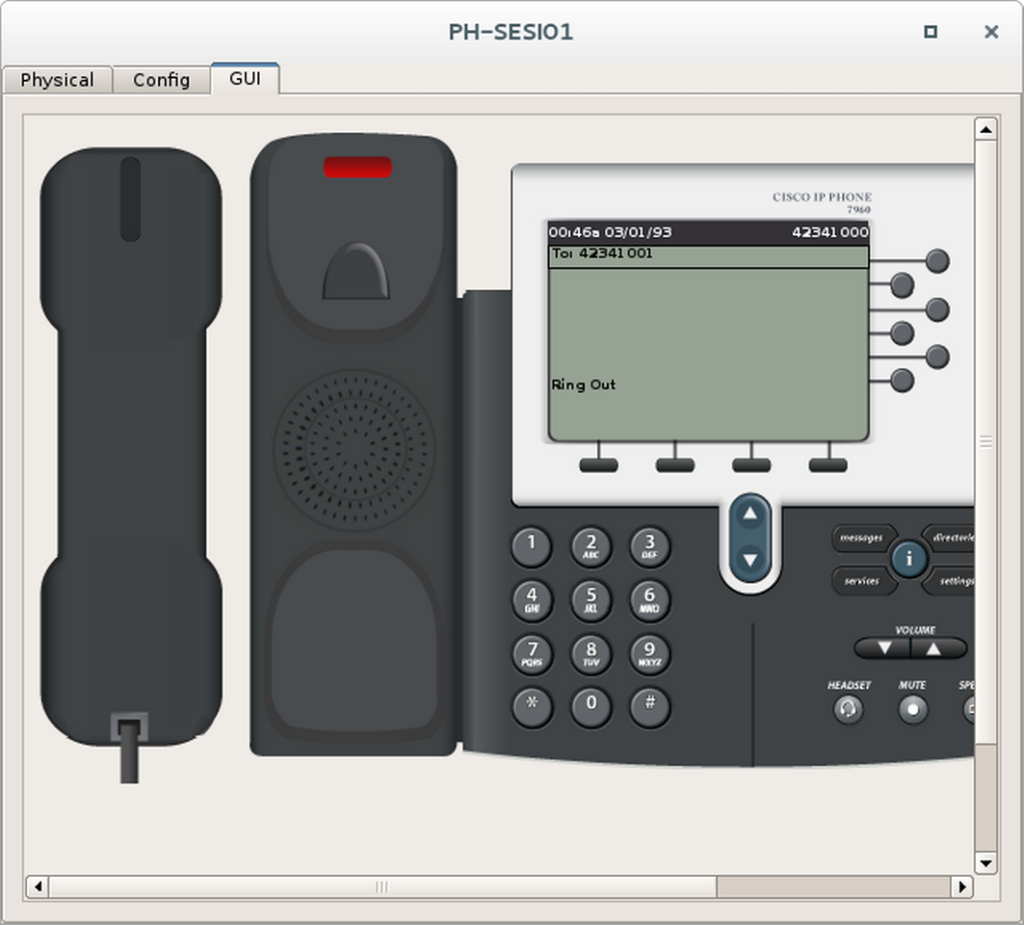
Etapa 2 – Fazer uma ligação telefônica
- Escolha dois telefones para fazer o teste de ligação.
- Dê um duplo clique neles e ponha-os lado a lado.
- Selecione a aba GUI de ambos.
- No primeiro telefone disque o ramal do segundo telefone e tire ele do gancho.
- Observe se o número discado aparece no segundo telefone.

TAREFA 6 – INTERLIGAR AS DUAS EMPRESAS
Etapa 1 – Configurar o link entre os dois roteadores
Observe que o comando abaixo necessita de interface serial na posição 0/0/0. Para isso você deve adicionar nos dois roteadores a interface WIC-1T.
Vá no PC-SENAI01, dê um duplo clique e acesse guia Desktop. Clique em terminal e depois clique em OK.
RT-SENAI01(config)#interface Serial0/0/0
RT-SENAI01(config-if)#description #Link com SESI#
RT-SENAI01(config-if)#ip address 10.20.30.1 255.255.255.252
RT-SENAI01(config-if)#clock rate 64000
RT-SENAI01(config-subif)#exit
RT-SENAI01(config)#ip route 0.0.0.0 0.0.0.0 Serial0/0/0
Vá no PC-SESI01, dê um duplo clique e acesse guia Desktop. Clique em terminal e depois clique em OK.
RT-SESI01(config)#interface Serial0/0/0
RT-SESI01(config-if)#description #Link com SENAI#
RT-SESI01(config-if)#ip address 10.20.30.2 255.255.255.252
RT-SESI01(config-subif)#exit
RT-SESI01(config)#ip route 0.0.0.0 0.0.0.0 Serial0/0/0
Após essa configuração temos link e roteamento entre as duas empresas. Agora precisamos configurar os Call Managers para se comunicarem.
Etapa 2 – Configurar a interligação entre as duas centrais telefônicas (CMEs)
Vá no PC-SENAI01, dê um duplo clique e acesse guia Desktop. Clique em terminal e depois clique em OK e digite:
RT-SENAI01(config)#dial-peer voice 1 voip
RT-SENAI01(config-dial-peer)#destination-pattern 42341000
RT-SENAI01(config-dial-peer)#session target ipv4:172.16.15.254
RT-SENAI01(config-dial-peer)#exit
RT-SENAI01(config)#dial-peer voice 2 voip
RT-SENAI01(config-dial-peer)#destination-pattern 42341001
RT-SENAI01(config-dial-peer)#session target ipv4:172.16.15.254
RT-SENAI01(config-dial-peer)#exitVá no PC-SESI01, dê um duplo clique e acesse guia Desktop. Clique em terminal e depois clique em OK e digite:
RT-SESI01(config)#dial-peer voice 1 voip
RT-SESI01(config-dial-peer)#destination-pattern 32341000
RT-SESI01(config-dial-peer)#session target ipv4:192.168.15.254
RT-SESI01(config-dial-peer)#exit
RT-SESI01(config)#dial-peer voice 2 voip
RT-SESI01(config-dial-peer)#destination-pattern 32341001
RT-SESI01(config-dial-peer)#session target ipv4:192.168.15.254
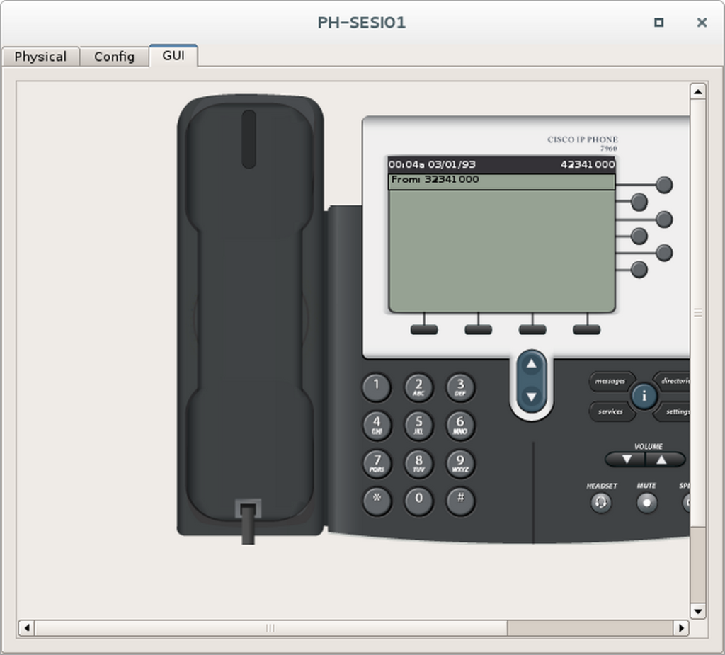
RT-SESI01(config-dial-peer)#exitEtapa 3 – Fazer uma ligação telefônica
- Escolha um telefone de cada empresa para fazer o teste de ligação.
- Dê um duplo clique neles e ponha-os lado a lado.
- Selecione a aba GUI de ambos.
- No primeiro telefone disque o ramal do segundo telefone e tire ele do gancho.
- Observe se o número discado aparece no segundo telefone, conforme exemplos abaixo.