Diagrama de topologia
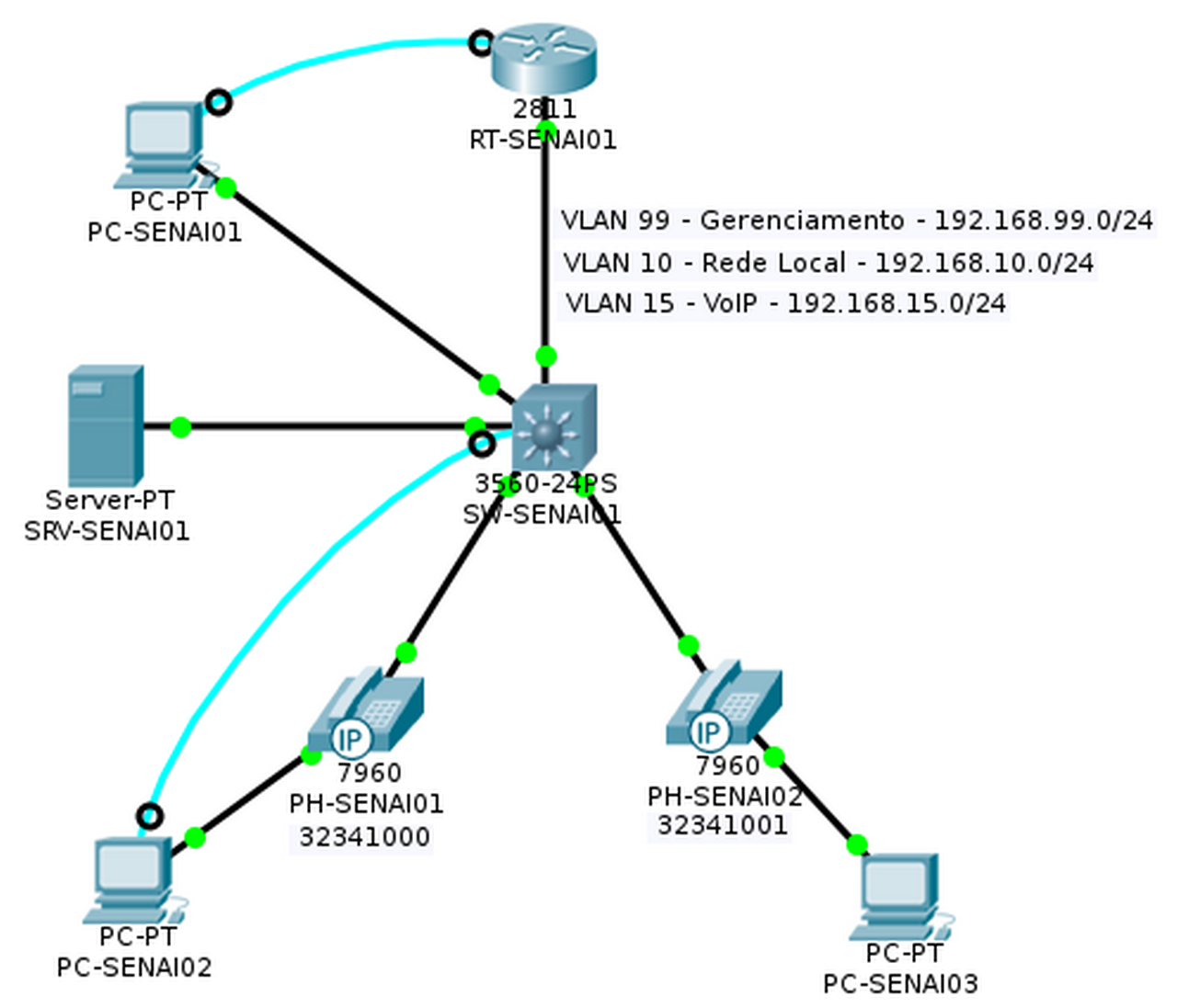
Tabela de endereçamento fixo
|
Dispositivo |
Interface |
Endereço IP |
Máscara de sub-rede |
Gateway padrão |
|
SW-SENAI01 |
VLAN99 |
192.168.99.1 |
255.255.255.0 |
N/A |
|
RT-SENAI01 |
Fa0/0.10 |
192.168.10.254 |
255.255.255.0 |
N/A |
|
RT-SENAI01 |
Fa0/0.15 |
192.168.15.254 |
255.255.255.0 |
N/A |
|
RT-SENAI01 |
VLAN99 |
192.168.99.2 |
255.255.255.0 |
N/A |
|
SRV-SENAI01 |
Fa0 |
192.168.10.250 |
255.255.255.0 |
192.168.10.254 |
Os outros dispositivos vão receber IP pelo serviço de DHCP.
OBJETIVOS DE APRENDIZAGEM
- Configurar topologia física de rede para telefonia IP
- Configurar VLANs de gerenciamento
- Configurar um servidor DNS
- Configurar um servidor de DHCP
- Configurar um serviço de telefonia
- Associar os ramais aos telefones
- Simular uma ligação de telefonia IP
INTRODUÇÃO
Esta atividade vai ensinar como configurar o serviço de telefonia IP em um ambiente cisco, explorando novos comandos. Também vai ensinar como configurar um servidor de DHCP para telefones IP. Esta é a prática 1 de 2. Na prática 2 vamos rever os comandos e também mostrarei como fazer um entrocamento entre dois sites, simulando assim comunicação entre duas empresas por exemplo. Esta prática foi totalmente desenvolvida por mim enquanto eu ministrava aulas na Entidade SENAI, por isso usei os nomes como exemplos.
TAREFA 1 – CONFIGURAR TOPOLOGIA FÍSICA
Etapa 1 – Cabear a rede
- Conectar a interface Fa0/0 de RT-SENAI01 à interface Fa0/24 de SW-SENAI01
- Conectar a interface Fa0/1 de SW-SENAI01 à interface Fa0 de PC-SENAI01
- Conectar a interface Fa0/2 de SW-SENAI01 à interface de Switch do telefone PH-SENAI01
- Conectar a interface Fa0/3 de SW-SENAI01 à interface de Switch do telefone PH-SENAI02
- Conectar a interface PC do telefone PH-SENAI01 à interface Fa0 do PC-SENAI02
- Conectar a interface PC do telefone PH-SENAI02 à interface Fa0 do PC-SENAI03
- Conectar a interface Fa0 de SRV-SENAI01 à interface Fa0/4 de SW-SENAI01
- Conectar a interface RS 232 de PC-SENAI01 a inter face de Console de RT-SENAI01
- Conectar a interface RS 232 de PC-SENAI02 a inter face de Console de SW-SENAI01
Etapa 2 – Nomear e colocar legendas no diagrama
- Altere o Display Name dos PCs conforme o diagrama de topologia acima.
- Coloque em legendas os números de telefone embaixo dos telefones.
- Coloque as legendas descritivas de VLANs conforme o diagrama de topologia acima.
TAREFA 2 – CONFIGURAR IP DO SERVIDOR DE DNS
Um serviço de DNS normalmente é configurado em um servidor. Portanto, temos no diagrama o servidor SRV-SENAI01, que em uma rede real, serviria como máquina principal de resolução de nomes na rede.
Etapa 1 – Configurar o IP do Servidor
- Dê um duplo clique em SRV-SENAI01 e, navegue até a guia DESKTOP
- Dê um duplo clique em IP CONFIGURATION
- Configure os campos conforme imagem abaixo
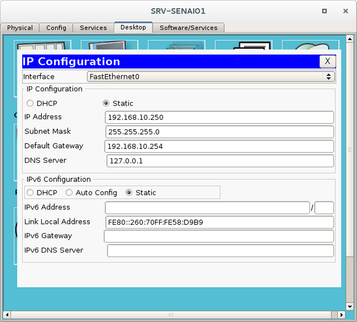
Note que o IP do DNS Server aponta para ele mesmo (127.0.0.1). Sempre devemos configurar um servidor que hospeda um serviço de DNS dessa forma.
TAREFA 3 – CONFIGURAR O SW-SENAI01
Etapa 1 – Fazer a configuração básica
Vá no PC-SENAI02, dê um duplo clique e acesse guia Desktop. Clique em terminal e depois clique em OK.
Switch>enable
Switch#conf t
Enter configuration commands, one per line. End with CNTL/Z.
Switch(config)#hostname SW-SENAI01
SW-SENAI01(config)#no ip domain lookup
SW-SENAI01(config)#service password-encryption
SW-SENAI01(config)#enable secret sw*123
SW-SENAI01(config)#line console 0
SW-SENAI01(config-line)#password console*123
SW-SENAI01(config-line)#login
SW-SENAI01(config-line)#exit
SW-SENAI01(config)#line vty 0 4
SW-SENAI01(config-line)#password vty*123
SW-SENAI01(config-line)#login
SW-SENAI01(config-line)#exit
SW-SENAI01(config)#ip default-gateway 192.168.10.254
Etapa 2 - Configurar um aviso de acesso
Um aviso de acesso permite identificarmos no acesso remoto se estamos acessando o dispositivo correto da rede.
SW-SENAI01(config)#banner motd &
Enter TEXT message. End with the character '&'.
************************************************
 !!!SW-SENAI01 - ACESSO RESTRITO!!!
************************************************
&
Etapa 3 – Criar as VLANs
SW-SENAI01(config)#vlan 10
SW-SENAI01(config-vlan)#name VLAN-Rede-Local
SW-SENAI01(config-vlan)#exit
SW-SENAI01(config)#vlan 15
SW-SENAI01(config-vlan)#name VLAN-VoIP
SW-SENAI01(config-vlan)#exit
SW-SENAI01(config)#vlan 99
SW-SENAI01(config-vlan)#name VLAN-Gerenciamento
SW-SENAI01(config-vlan)#exit
Etapa 4 - Configurar a VLAN de Gerenciamento
SW-SENAI01(config)#
SW-SENAI01(config)#interface VLAn 1
SW-SENAI01(config-if)#no ip address
SW-SENAI01(config-if)#shutdown
SW-SENAI01(config-if)#exit
SW-SENAI01(config)#interface vlan 99
SW-SENAI01(config-if)#
%LINK-5-CHANGED: Interface Vlan99, changed state to up
SW-SENAI01(config-if)#ip address 192.168.99.1 255.255.255.0
SW-SENAI01(config-if)#exitEtapa 5 - Configurar as interfaces
SW-SENAI01(config)#
SW-SENAI01(config)#interface range fastEthernet 0/1-23
SW-SENAI01(config-if-range)#switchport access vlan 10
SW-SENAI01(config-if-range)#switchport mode access
SW-SENAI01(config-if-range)#switchport voice vlan 15
SW-SENAI01(config-if-range)#exit
SW-SENAI01(config)#
SW-SENAI01(config)#interface fastEthernet 0/24
SW-SENAI01(config-if)#switchport trunk native vlan 99
SW-SENAI01(config-if)#switchport trunk encapsulation dot1q
SW-SENAI01(config-if)#switchport mode trunk
Command rejected: An interface whose trunk encapsulation is "Auto" can not be configured to "trunk" mode.
SW-SENAI01(config-if)#exitEtapa 6 – Verificar se as VLANs foram criadas
SW-SENAI01#show vlan brief
VLAN Name                         Status    Ports
---- ---------------------------- --------- -------------------------------
1    default                      active    Gig0/1, Gig0/2
10   VLAN-Rede-Local              active    Fa0/1, Fa0/2, Fa0/3, Fa0/4
                                            Fa0/5, Fa0/6, Fa0/7, Fa0/8
                                            Fa0/9, Fa0/10, Fa0/11, Fa0/12
                                            Fa0/13, Fa0/14, Fa0/15, Fa0/16
                                            Fa0/17, Fa0/18, Fa0/19, Fa0/20
                                            Fa0/21, Fa0/22, Fa0/23
15   VLAN-VoIP                    active
99   VLAN-Gerenciamento           active
1002 fddi-default                 act/unsup
1003 token-ring-default           act/unsup
1004 fddinet-default              act/unsup
1005 trnet-default                act/unsup
Etapa 7 - Verificar se a VLAN 99 foi conigurada
SW-SENAI01#show interfaces vlan 99
Vlan99 is up, line protocol is up
  Hardware is CPU Interface, address is 00d0.bab5.d083 (bia 00d0.bab5.d083)
  Internet address is 192.168.99.1/24
  MTU 1500 bytes, BW 100000 Kbit, DLY 1000000 usec,reliability 255/255, txload 1/255, rxload 1/255
  Encapsulation ARPA, loopback not set
  ARP type: ARPA, ARP Timeout 04:00:00
  Last input 21:40:21, output never, output hang never
  Last clearing of "show interface" counters never
  Input queue: 0/75/0/0 (size/max/drops/flushes); Total output drops: 0
  Queueing strategy: fifo
  Output queue: 0/40 (size/max)
  5 minute input rate 0 bits/sec, 0 packets/sec
  5 minute output rate 0 bits/sec, 0 packets/sec
     1682 packets input, 530955 bytes, 0 no buffer
     Received 0 broadcasts (0 IP multicast)
     0 runts, 0 giants, 0 throttles
     0 input errors, 0 CRC, 0 frame, 0 overrun, 0 ignored
     563859 packets output, 0 bytes, 0 underruns
     0 output errors, 23 interface resets
     0 output buffer failures, 0 output buffers swapped out
Etapa 8 – Salvar as configurações
SW-SENAI01#write
Building configuration...
[OK]
SW-SENAI01#
TAREFA 4 - CONFIGURAR O ROTEADOR RT-SENAI01
Etapa 1 – Fazer a configuração básica
Vá no PC-SENAI01, dê um duplo clique e acesse guia Desktop. Clique em terminal e depois clique em OK.
Router>enable
Router#conf t
Enter configuration commands, one per line. End with CNTL/Z.
Router(config)#hostname RT-SENAI01
RT-SENAI01(config)#no ip domain lookup
RT-SENAI01(config)#service password-encryption
RT-SENAI01(config)#enable secret rt*123
RT-SENAI01(config)#line console 0
RT-SENAI01(config-line)#password console*123
RT-SENAI01(config-line)#login
RT-SENAI01(config-line)#exit
RT-SENAI01(config)#line vty 0 4
RT-SENAI01(config-line)#password vty*123
RT-SENAI01(config-line)#login
RT-SENAI01(config-line)#exit
Etapa 2 - Configurar um aviso de acesso
Um aviso de acesso permite identificarmos no acesso remoto se estamos acessando o dispositivo correto da rede.
RT-SENAI01(config)#banner motd &
Enter TEXT message. End with the character '&'.
************************************************
 !!!RT-SENAI01 - ACESSO RESTRITO!!!
************************************************
&
Etapa 3 – Configurar as interfaces
RT-SENAI01(config)#interface fastEthernet 0/0
RT-SENAI01(config-if)#no shutdown
RT-SENAI01(config-if)#exit
RT-SENAI01(config)#interface fastEthernet 0/0.99
RT-SENAI01(config-subif)#description #Sub-Interface de Gerenciamento#
RT-SENAI01(config-subif)#encapsulation dot1Q 99 native
RT-SENAI01(config-subif)#ip address 192.168.99.2 255.255.255.0
RT-SENAI01(config-subif)#exitRT-SENAI01(config)#interface fastEthernet 0/0.10
RT-SENAI01(config-subif)#description #Sub-Interface da VLAN de Rede Local#
RT-SENAI01(config-subif)#encapsulation dot1Q 10
RT-SENAI01(config-subif)#ip address 192.168.10.254 255.255.255.0
RT-SENAI01(config-subif)#exitRT-SENAI01(config)#interface fastEthernet 0/0.15
RT-SENAI01(config-subif)#description #Sub-Interface da VLAN de VoIP#
RT-SENAI01(config-subif)#encapsulation dot1Q 15
RT-SENAI01(config-subif)#ip address 192.168.15.254 255.255.255.0
RT-SENAI01(config-subif)#exitEtapa 4 – Verificar a configuração das interfaces
Lembre-se que a rede 192.168.10.0 é para computadores, e a rede 192.168.15.0 é para telefones.
RT-SENAI01#show ip interface brief
Interface          IP-Address     OK? Method Status                Protocol
FastEthernet0/0    unassigned     YES unset  up                    up
FastEthernet0/0.10 192.168.10.254 YES manual up                    up
FastEthernet0/0.15 192.168.15.254 YES manual up                    up
FastEthernet0/0.99 192.168.99.2   YES manual up                    up
FastEthernet0/1    unassigned     YES unset  administratively down down
Vlan1              unassigned     YES unset  administratively down down
Etapa 5 – Configurar o serviço de DHCP para as VLANs
RT-SENAI01(config)#ip dhcp excluded-address 192.168.10.250
RT-SENAI01(config)#ip dhcp excluded-address 192.168.10.254
RT-SENAI01(config)#ip dhcp excluded-address 192.168.15.254
RT-SENAI01(config)#ip dhcp pool rede-local-senai
RT-SENAI01(dhcp-config)#network 192.168.10.0 255.255.255.0
RT-SENAI01(dhcp-config)#default-router 192.168.10.254
RT-SENAI01(dhcp-config)#dns-server 192.168.10.250
RT-SENAI01(dhcp-config)#exitRT-SENAI01(config)#ip dhcp pool rede-voip-senai
RT-SENAI01(dhcp-config)#network 192.168.15.0 255.255.255.0
RT-SENAI01(dhcp-config)#default-router 192.168.15.254
RT-SENAI01(dhcp-config)#option 150 ip 192.168.15.254
RT-SENAI01(dhcp-config)#exitEtapa 6 – Verificar a distribuição de IPs
RT-SENAI01#show ip dhcp binding
IP address    Client-ID/       Lease expiration Type
              Hardware address
192.168.10.1  00E0.F79D.9D7A    --              Automatic
192.168.10.2  0003.E4DA.219B    --              Automatic
192.168.15.2  0001.97C8.C846    --              Automatic
192.168.15.1  0050.0F6B.D115    --              Automatic
Etapa 7 – Configurar o serviço de telefonia
RT-SENAI01(config)#telephony-service
RT-SENAI01(config-telephony)#max-ephones 10
RT-SENAI01(config-telephony)#max-dn 10
RT-SENAI01(config-telephony)#ip source-address 192.168.15.254 port 2000
RT-SENAI01(config-telephony)#auto assign 1 to 10
RT-SENAI01(config-telephony)#exit
Etapa 8 – Configurar os ramais de telefone
RT-SENAI01(config)#ephone-dn 1
RT-SENAI01(config-ephone-dn)#%LINK-3-UPDOWN: Interface ephone_dsp DN 1.1, changed state to up
RT-SENAI01(config-ephone-dn)#number 32341000
RT-SENAI01(config-ephone-dn)#exit
RT-SENAI01(config)#ephone-dn 2
RT-SENAI01(config-ephone-dn)#%LINK-3-UPDOWN: Interface ephone_dsp DN 2.1, changed state to up
RT-SENAI01(config-ephone-dn)#number 32341001
RT-SENAI01(config-ephone-dn)#exitEtapa 9 – Salvar as configurações
RT-SENAI01#write
Building configuration...
[OK]
RT-SENAI01#
TAREFA 5 – TESTAR A CONFIGURAÇÃO
Nesse ponto da configuração, os telefones IPs já devem ter se auto-registrado e se associado a um ramal. Para verificar se isso realmente aconteceu, precisamos executar a etapa abaixo.
Etapa 1 – Verificar a configuração dos telefones
RT-SENAI01#show ephone
ephone-1 Mac:0001.97C8.C846 TCP socket:[1] activeLine:0 REGISTERED in SCCP ver 12 and Server in ver 8 mediaActive:0 offhook:0 ringing:0 reset:0 reset_sent:0 paging 0 debug:0 caps:8
IP:192.168.15.2 1025 7960 keepalive 43 max_line 2
 button 1: dn 1 number 32341000 CH1 IDLE
ephone-2 Mac:0050.0F6B.D115 TCP socket:[1] activeLine:0 REGISTERED in SCCP ver 12 and Server in ver 8 mediaActive:0 offhook:0 ringing:0 reset:0 reset_sent:0 paging 0 debug:0 caps:8
IP:192.168.15.1 1025 7960 keepalive 43 max_line 2
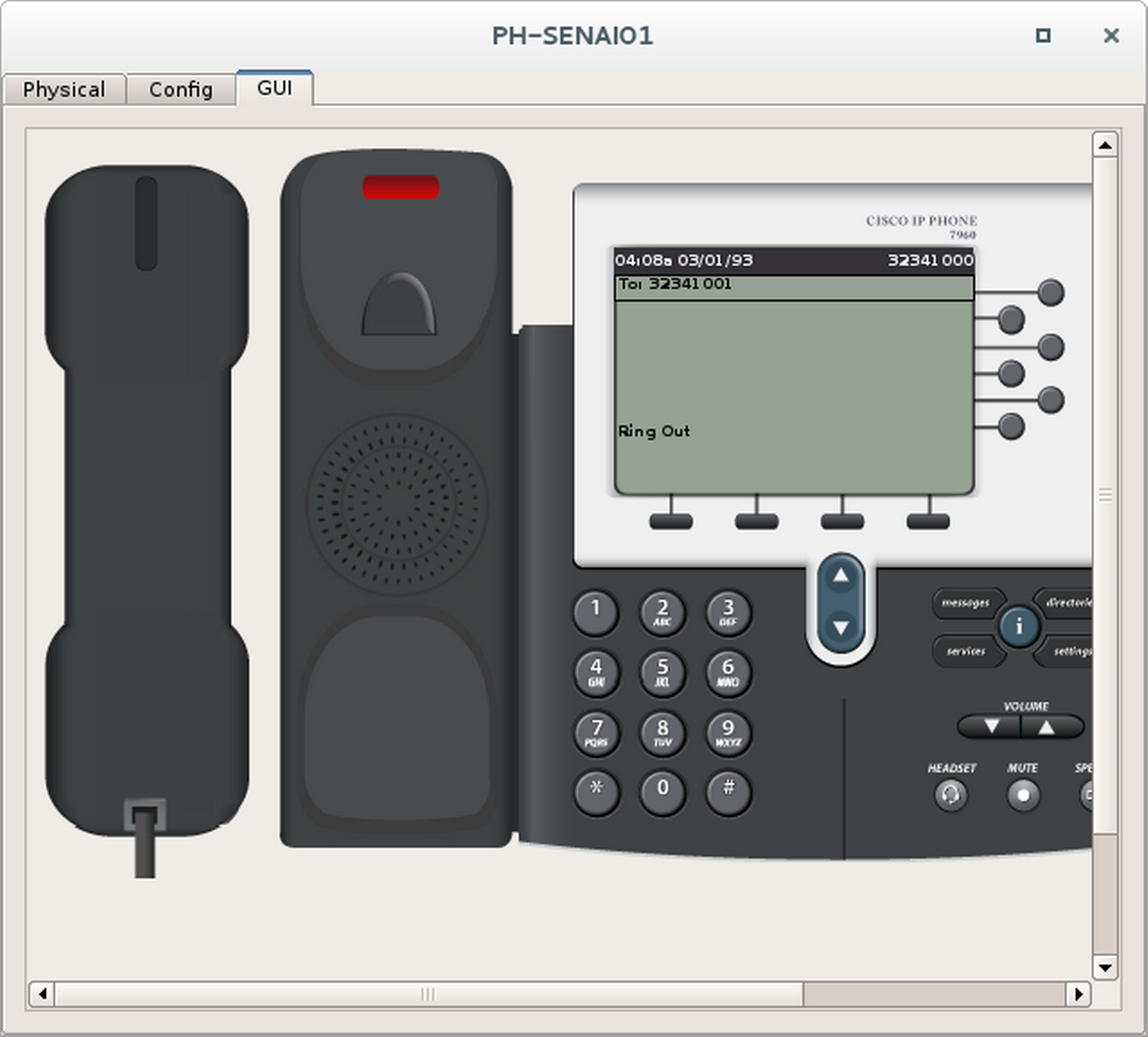
button 1: dn 2 number 32341001 CH1 IDLEEtapa 2 – Fazer uma ligação telefônica
- Escolha dois telefones para fazer o teste de ligação.
- Dê um duplo clique neles e ponha-os lado a lado.
- Selecione a aba GUI de ambos.
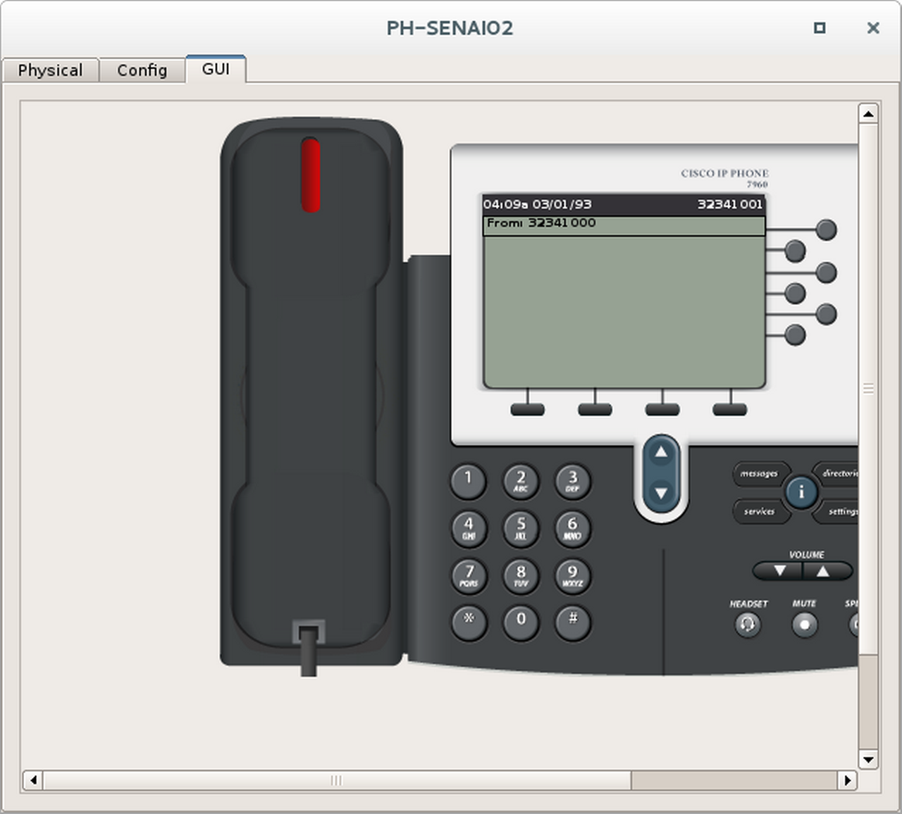
- No primeiro telefone disque o ramal do segundo telefone e tire ele do gancho.
- Observe se o número discado aparece no segundo telefone.